

The computer block diagram means the basic structure of the computer. how a computer system will look like. what element computer system consisting of.
If you take a basic architecture of a computer or a basic block of a computer how it will look like.
What’s in it for me?
- Computer block diagram (explanation)
- Computer Block diagram picture.
- CPU (central processing unit)
- ALU (Arithmetic logic unit)
- Control Unit
- Registers
- Input unit
- Output unit
- Memory unit
- FAQ.
Computer block diagram (explanation) –
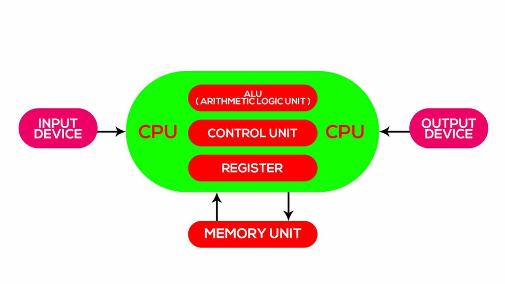
This a very basic topic and this will give you information regarding the computer block diagram. It consists of the first unit which is an input device.
those input devices would be a mouse, keyboard, or maybe a joystick. In a basic computer, we need an input device. after the input device, the next one is the CPU.
The CPU is divided into three parts means the internal part of the CPU is divided into three parts. ALU ( arithmetic logic unit) second part is the control unit.
The third part is registered. That means the cpu consisting of 3 basic units that are arithmetic logic unit ALU control unit, and registers.
After this input and CPU, the next one is the output once you do the input once you process the data you are going to see the data at a particular device.
For a basic computer, the basic output device is some display device like led display or sound system display all these things come in the output device.
Basic introduction of computer block diagram –
Coming to the computer system basic input device is the keyboard and the mouse and the basic output device is the monitor.
In CPU arithmetical logic unit is a responsible device to do all arithmetic and logical operations.
Arithmetic operation is multiplication, division, addition and subtraction, and some of increment and detriment operation.
Coming to the logical operation so have 7 basic logical operations are there NAND gate, NOR gate, NOT gate, OR gate, AND gate, XOR gate, an XNOR gate.
Operations done in a logical unit.
It also performs some sudden operations like shifting operation and rotation operation also. So arithmetic and logic unit is a responsible device which will do all the arithmetic and logic operation.
To perform this arithmetic and logic operation we require data storage elements, for example, 2+ 2 then 2 should be stored.
Those values stored in the register. Register are temporary storage devices and first processing devices are these that hold data temporarily for do sudden operation.
After this next one is the control unit. Control unit is the responsible device to control all these operations like – what kind of data is processing?
what kind of data transferring between them. So all these processing are doing in the control unit.
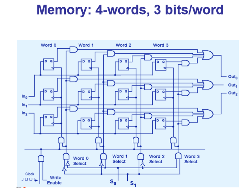
After this, the CPU block has another element which is memory. Registers means a data storage element, the flip-flop is a method in which you can store 1 bit like 0 or 1.
A group of flip-flops is called registers.
If you want to store 4-bit data then you need 4 registers, 4 registers a formed by combining the flip flop and these are temporary storage devices.
So we need a device to store data for a long time for this we connect memory to the computer and memory is connected to CPU in bi directonal way ad cpu take and store data in the memory.
Computer block diagram image –

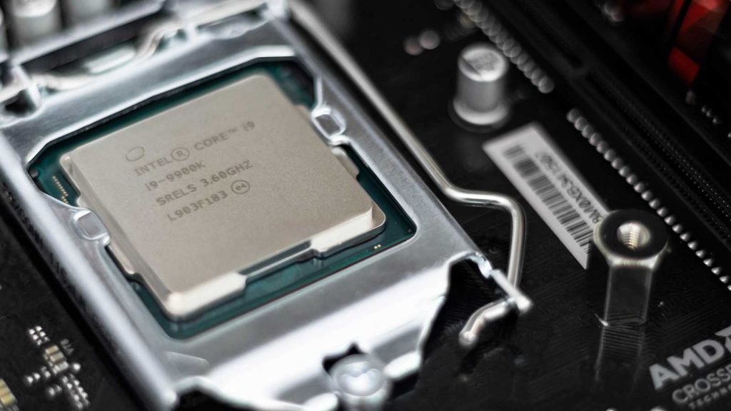
CPU (Central Processing Unit)
The CPU -the centerpiece of the computer’s architecture—
is in charge of executing the instructions of the currently loaded program. This is an important part of the Computer Block diagram.
Also, These instructions tell the CPU to carry out various calculations, to read and write values from and into the memory,
and to conditionally jump to execute other instructions in the program.
The CPU executes these tasks using three main hardware elements: an Arithmetic-Logic Unit (ALU ), a set of registers, and a control unit.
Arithmetic Logic Unit –
The ALU is built to perform all the low-level arithmetic
and logical operations featured by the computer.
For instance, a typical ALU can add two numbers, test whether a number is positive, manipulate the bits in a word of data, and so on.
Thus, every CPU is provided with a small set of high-speed registers, each capable of holding a single word.
Control Unit –
A computer instruction is represent as a binary code, 16,32, or 64 bits wide.
Before such instruction is performed, it must be decoded, and the data set in it must be signal different hardware devices (ALU, registers, memory).
The instruction decoding is done by the control unit, which is also responsible for deciding which instruction to get and execute next.
The CPU operation can now be specified as a repeated loop. Also, fetch an instruction
(word) from memory, decode it, execute it, fetch the next instruction, and so on.
Registers –

Memory access is a slow operation.
For example – When the CPU is told to get the contents of address ( j ) of the memory, the following process occurs.
(a) j travels from the CPU to the RAM;
(b) The RAM’s direct-access logic selects the memory register whose
address is j;
(c) The contents of RAM[ j] travel back to the CPU.
Registers provide the same service—data retrieval and storage—without the round-trip travel and search expenses. First, the registers reside physically inside the CPU chip, so accessing them is almost instantaneous.
Data registers in Computer block diagram
These registers give the CPU short-term memory services. For example, when calculating the value of ( a – b ) * c, we must first compute and remember
the value of ( a – b ).
Although, this result can be temporarily stored in some memory
location, a better solution is to store it locally inside the CPU-in a data register.
Addressing registers –
The CPU has to continuously access the memory in order to read data and write data. In every one of these operations, so, we must specify which individual memory word has to be accessed, namely, supply an address.
In some cases, this address appears as part of the current instruction, while in others it
depends on the execution of a previous instruction.
Program counter register –
When executing a program, the CPU must always keep track of the address of the next instruction that must be fetched from the instruction memory.
The contents of the PC are then used as the address for fetching instructions from the instruction memory.
Input unit –

input is any kind of data given to the computer by the use of any medium and this medium is called an input device.
For example- input data from printer.
Thus, this is the process of entering data and programs in the computer system. Hence You know that a computer is an electronic machine like any other machine which takes inputs as raw data.
performs some processing giving out processed data. Therefore, the input unit takes data from us to the computer in an organized manner for processing.
Output unit –
Let me first tell you about what is an output. An output is a thing that we get after
processing it by the processor so when you give some input to the computer.
This is the process of producing results from the data for getting useful information.
Similarly the output produced by the computer after processing must also be kept
I hope so, you understand the Computer Block Diagram as well. If yes do a comment and tell us
Memory unit –
The memory of a machine holds two types of information. Data items and programming instructions.
In spite of their different functions though,
A continuous array of cells of some fixed width, also called words or locations, each having a unique address.
Hence, an individual word (representing either a data item or an
instruction) is specified by supplying its address.
Data Memory – In Computer block diagram
High-level programs manipulate abstract artifacts like variables,
arrays, and objects.
When translated into machine language, these data abstractions
become a series of binary numbers, stored in the computer’s data memory.
most important In most of the cases, we retrieve the word’s value. In the latter case, we store a new value into the selected location, erasing the old value.
Instruction Memory – Computer block diagram
When translated into machine language, each high-level command becomes a series of binary words, representing machine language instructions.
Also, In each step of the computer’s operation, the CPU fetches a word from the instruction memory.
Also, decodes it, executes the specified instruction, and figures out which instruction to execute next.
Thus, changing the contents of the instruction memory has the
effect of completely changing the computer’s operation.
Have a doubt in the Computer block diagram let us know in the comment section.
Also read – Computer memory types
FAQ –
computer is a electronic machine made on 6 main units which is CPU ( Central Processing Unit ), ALU (Arithmetic Logic Unit), Control unit, Memory Unit, Input Unit, Output Unit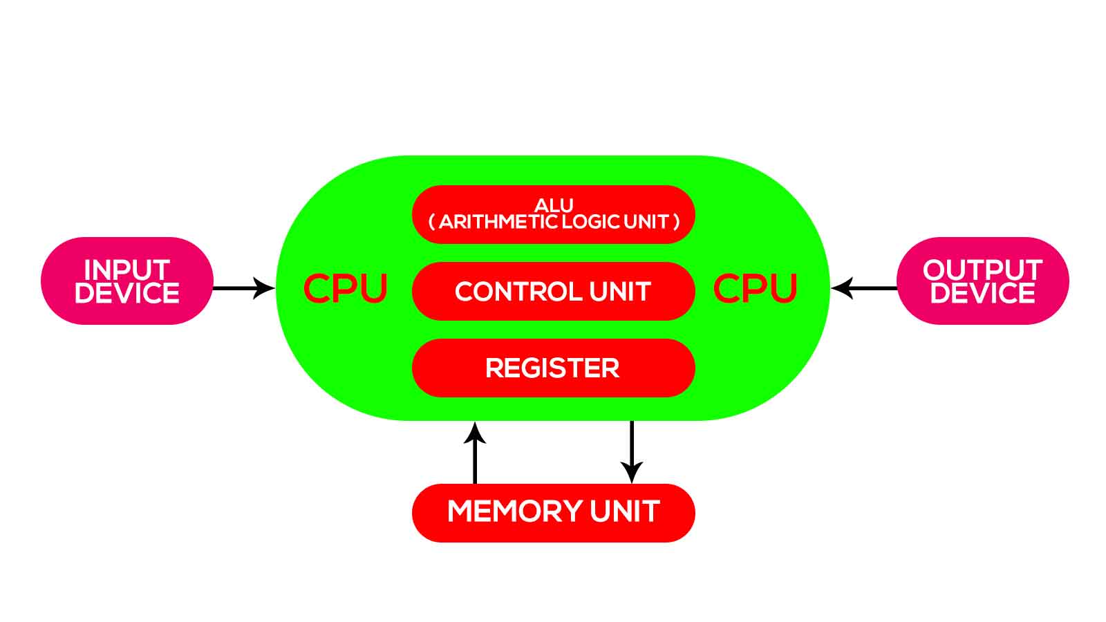

Control unit is the responsible device to control all these operations like – what kind of data is processing? what kind of data transferring between them. so all these processing are doing in the control unit.
After this, the CPU block has another element which is memory. Registers means a data storage element, the flip-flop is a method in which you can store 1 bit like 0 or 1. A group of flip-flops is called registers.
The CPU -the centerpiece of the computer’s architecture—is in charge of executing the instructions of the currently loaded program. This is an important part of the Computer Block diagram.
Computers interact with their external environments using a diverse array of input and output (I/O) devices. These include screens, keyboards, printers, scanners, network interface cards, CD-ROMs,


Computer Expert | Pursuing Computer science | web developer | Graphic designer | Digital marketer soon
I love to learn new stuffs.
Have a good day!


