

The logic gates are commonly used in Integrated Circuits(IC). However, the logic gate is an electronic component, which is made of resister and triode or diode. Also, they can control the current according to a particular equation.
INDEX
- What are the Logic Gates?
- Invention of Logic Gates
- Types of the Logic Gates
- The Universal Gates
- Logic gate and their IC’s number
- Conclusion
- FAQs
What are the Logic Gates?
The Logic Gates are an electronic component, which is made of resister and triode or diode. They can control the current according to a particular equation.
It is commonly used in Integrated Circuits(IC). Generally, they have two inputs and one output. So, we consider the inputs and output in binary format. If we found the current it is true and if not so it’s false. Also, they are one type of switch actually, which takes inputs, do the operation according to its function and give output.


Invention of Logic Gates
Charles Sanders Peirce(known as the father of pragmatism) founded that the logical operations can be done by electronic switching circuits.
Types of the Logic Gates
There are basic 7 types of gates available. Which are AND gate, OR gate, NOT gate, NAND gate, NOR gate, XOR gate and XNOR gate.
So, let’s start…
1. AND gate


Firstly, there is two switches, which we can consider as inputs of gates. The switches are in series, if both switch is ON(connected) then and then only the bulb will glow. If any of one switch is OFF(disconnected) then the bulb will not glow. However, we can understand this thing by a truth table given below.


NOTE: Firstly, this example of bulb is given only to understand the concept easily. However, gates are actually made of resister and triode (transistors) or diode.
The bulb will only glows when A and B both of the switches are ON. Therefore, we call it as AND gate.
Boolean expression/Output: A · B
However, the ( · ) represents AND gate operation between A and B.
Truth Table of AND gate
| A | B | Output |
|---|---|---|
| 0 | 0 | 0 |
| 0 | 1 | 0 |
| 1 | 0 | 0 |
| 1 | 1 | 1 |
Here;
A= first input
B = second input
Output = A · B
2. OR gate

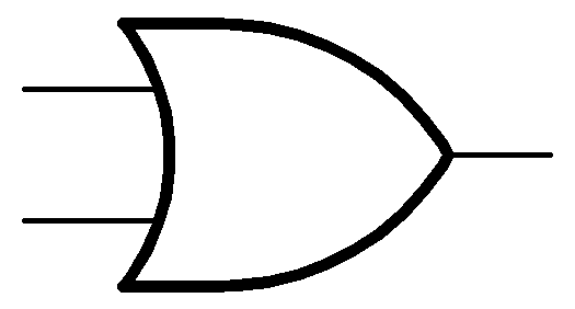
Firstly, there is two switches connected in parallel. If one switch is ON and other is OFF then it is okay. Because, the Bulb will glow. So, the bulb will glow in all condition except both switches are OFF.
Bulb will glow when A or B or both switches are ON. Therefore, we call it as OR gate.


Boolean expression/Output: A + B
However, the ( + ) represents OR gate operation between A and B.
Truth Table of OR gate
| A | B | Output |
|---|---|---|
| 0 | 0 | 0 |
| 0 | 1 | 1 |
| 1 | 0 | 1 |
| 1 | 1 | 1 |
3. NOT gate


Firstly, there is one switch connected parallel with bulb. The bulb will glow when the switch is OFF and bulb will not glow when switch is ON. The bulb will only ON when switch is OFF and Bulb will OFF when switch is ON. NOT gate basically inverts the input. So, we can also call it inverter gate.
The bulb will only glow when A is OFF. Therefore, we call it as NOT gate.


Boolean expression/Output:
A
However, the ( ¯ ) represents NOT gate operation on A.
Truth Table of OR gate
| A | Output |
|---|---|
| 0 | 1 |
| 1 | 0 |
4. NAND gate


If we invert the outputs of AND gate, so that will be NAND gate’s output. Also, NOT gate’s output is invert of the input it get. But, if we connect NOT gate with AND gate as shown in below figure the output will be of NAND gate.
So basically, NAND gate is (NOT + AND) gate
Boolean expression/Output:
A · B
However, the ( · ) represents AND gate operation between A and B
However, the ( ¯¯ ) represents NOT gate operation on the output of A·B
Truth Table of NAND gate
| A | B | Output |
|---|---|---|
| 0 | 0 | 1 |
| 0 | 1 | 1 |
| 1 | 0 | 1 |
| 1 | 1 | 0 |
5. NOR gate

If we invert the outputs of OR gate, so that will be NOR gate’s output. However, NOT gate’s output is invert of the input it get. If we connect NOT gate with OR gate as shown in below figure, the output will be of NOR gate.
So basically, NAND gate is (NOT + OR) gate
Boolean expression/Output:
A + B
However, the ( + ) represents OR gate operation between A and B
However, the ( ¯¯ ) represents NOT gate operation on the output of A+B
Truth Table of NOR gate
| A | B | Output |
|---|---|---|
| 0 | 0 | 1 |
| 0 | 1 | 0 |
| 1 | 0 | 0 |
| 1 | 1 | 0 |
6. XOR gate (Exclusive OR gate)


This gate only give true output when only one of its input is true. It only give false output when its all inputs are same.
If XOR gate have two input so, if one input is true and other input is false then its output will be true. If its one input is false and other input is also false or If its one input is true and other input is also true then its output will be false.
Boolean expression/Output: A ⊕ B
However, the (⊕) represents XOR gate operation between A and B.
Truth Table of XOR gate
| A | B | Output |
|---|---|---|
| 0 | 0 | 0 |
| 0 | 1 | 1 |
| 1 | 0 | 1 |
| 1 | 1 | 0 |
7. XNOR gate (Exclusive NOR)


However, This gate is just a inversion of XOR gate. It only give false output when only one of its input is true.
This gate only give true output when its all inputs are same.
That means, if XOR gate have two input so, if one input is true and other input is false then its output will be false. If its one input is false and other input is also false or If its one input is true and other input is also true then its output will be true.
Boolean expression/Output:
A ⊕ B
However, the (⊕) represents XOR gate operation between A and B.
However, ( ¯¯ ) represents NOT gate operation on the output of A B
Truth Table of XNOR gate
| A | B | Output |
|---|---|---|
| 0 | 0 | 1 |
| 0 | 1 | 0 |
| 1 | 0 | 0 |
| 1 | 1 | 1 |
The Universal Gates
Universal gates can solve any Boolean function without help of any other gate. NAND gate and NOR gate, this two are universal gates.
What is a universal gates?
Universal gates are like Three Primary Colors(Red, Yellow, Blue). so, we can make any color we want by mixing that colors in appropriate quantity. Same way, we can make other gates by fixing the two universal gates(NAND and NOR) in appropriate manner.
Let’s see how we can make every other gates, with only use of universal gates(NAND and NOR).
Formation of other Gates by use of Universal Gates
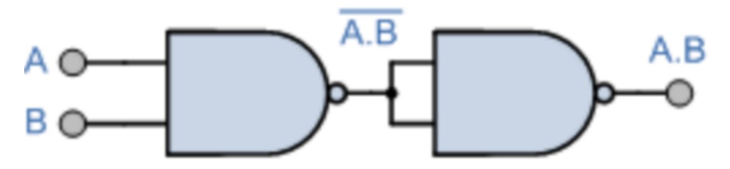
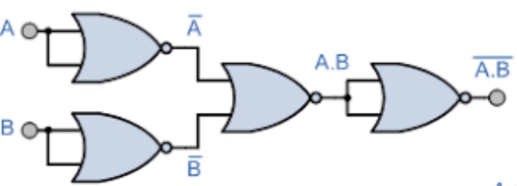
- AND gate
- Made with use of NAND gates
- Made with use of NOR gates
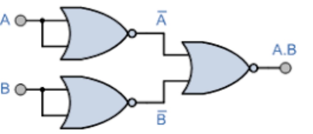
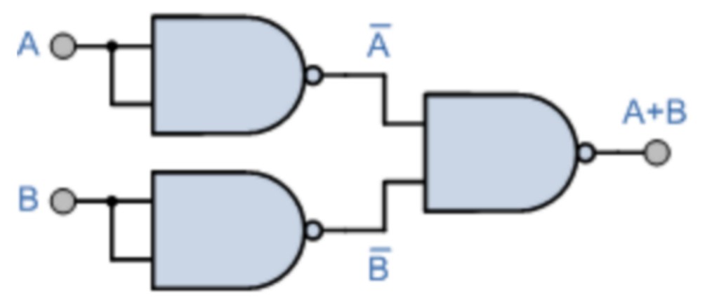
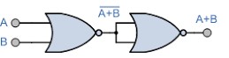
- OR gate
- Made with use of NAND gates
- Made with use of NOR gates
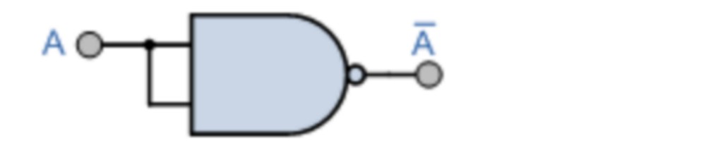
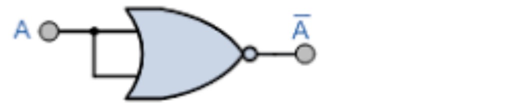
- NOT gate
- Made with use of NAND gates
- Made with use of NOR gates
- NAND gate
- Made with use of NOR gates
- NOR gate
- Made with use of NAND gates
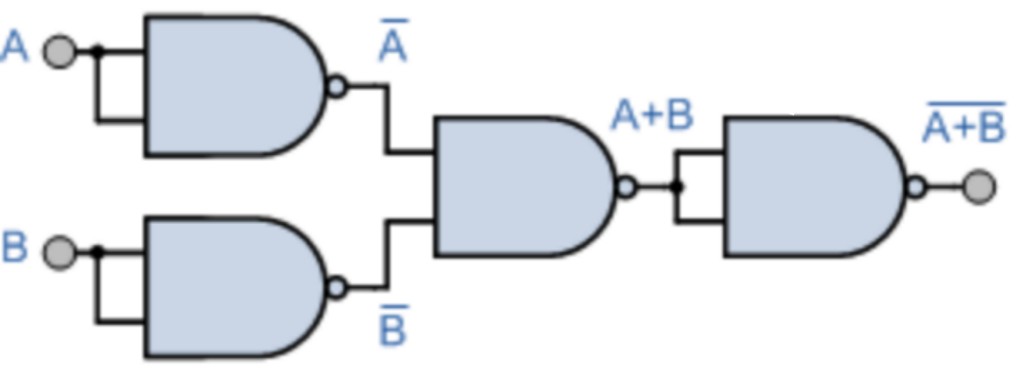
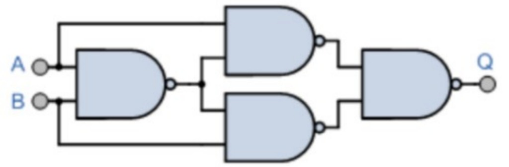
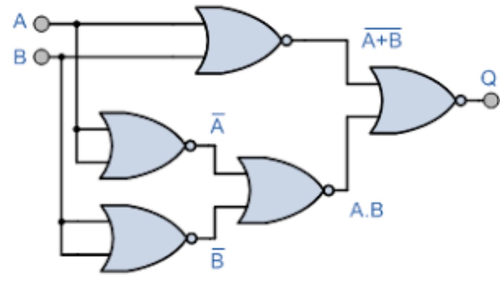
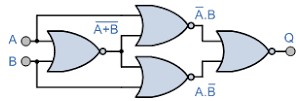
- XOR gate
- Made with use of NAND gates
- Made with use of NOR gates
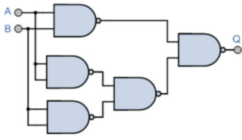
- XNOR gate
- Made with use of NAND gates
- Made with use of NOR gates


Circuits source: electronics-tutorials.ws
That’s why NAND gate and NOR gate are universal gates!
Logic gate and their IC’s number:
| Logic Gate | IC number |
|---|---|
| AND gate | 7408 |
| OR gate | 7432 |
| NOT gate | 7404 |
| NAND gate | 7400 |
| NOR gate | 7402 |
| XOR gate | 7486 |
| XNOR gate | 4077 |
Conclusion
Each basic gate works in some unique way, which is proved during this blog. However, we used the truth table to examine the operation of the basic logic gate. So, it is proved from blog that logic gates work in basis of Boolean Algebra. However, AND Gate, OR Gate and NOT Gate are the basic gates.
FAQs
They are called gates because they control the flow of signal. And their output is either 0 or 1, means true or false. However, their output is the result of their input(s). But, the simplest form of a logic gate is the negation gate. They are called logic gates because they are components of logic circuits.
Logic gates are used to define the state of the system that has many inputs and outputs so that more complex units are created such as arithmetic units, shift registers, memory elements etc. However, programs are written which manipulate these complex units giving what you see on the screen of your computer etc.
The principle of operation is that the circuit operates on just two voltage levels, called logic 0 and logic 1. When either of these voltage levels is applied to the inputs, the output of the gate responds by assuming a 1 or a 0 level, it is depending on the particular logic of the gate.
Firstly, the table used to represent the boolean expression of a logic gate function is commonly called a Truth Table. However, A logic gate truth table shows each possible input combination to the gate or circuit with the resultant output depending upon the combination of these input(s).
An Example of Boolean Logic at Work In Building Audiences. But, the Boolean operator “OR” is used to express that as long as one of two or more conditions are, met the value of a specified query is true.


Hi, I’m a Blogger & Web-Developer.
Done B.tech from Dharmsinh Desai University, Nadiad


